OES ENGINE 2
/JAMES FRANK OSTERBUR/ inventor-owner
Application #
18/952,324
Confirmation #
5133
Patent center #
68024057
Received
11/19/2024 3:05:37
abstract:
This is the architecture, for the basic engine design; expected; to be used in electrical generation. Its design is consistent with the originating OES engine, for this purpose. But without the architecture of distinguishing drawings; the patent is considered to be critically unsupported in an environment where any tiny change is considered to be an alternate invention; regardless of how similar it is. Consequently the development of distinguishing elements continues.
BACKGROUND: OES Engine 2
Includes drawings page 1 + 2
/James Frank Osterbur/ inventor-owner.
to establish the fundamentals, rather than the mechanical disciplines needed to align the basic parts into a common use machine. Therefore attention to detail is considered to be of limited value. While the basic compilation of parts; is granted a value which would otherwise be considered obvious. Limited complexity is used so the majority will not get lost.
the critical question is: if the design intent will be lost without a specific type of design for instruction. That being the basic design is expected to be roughly fifty cylinders around the same rotating wheel valving system; to produce roughly 12,000 horsepower, which can be manipulated, through the various stages of: disconnecting individual cylinders through clutching of some sort; to reduce that down to 1000 hp for less need usage; if desired.
SUMMARY:
to construct what is ultimately the starting stepping stones, for basic conceptions; so that all can be certain this is what was intended for this particular function, in this particular way. Whereas other versions of this OES engine remain untouched, and are as they are described.
SPECIFICATIONS:
the foundation for this invention is to further identify the basic architecture of larger than possible engines of this time. Machines capable of greatly increased horsepower require specialized, structural design work. Floor mounting/ ring structure suspension/ and so on. Machines that include “once it starts/ it will not be stopped”; unless something breaks. Machines that must be confined to realistic space limits. Are all versions of a secondary elevation; which allows the drafting of distinct conceptions. Which includes how we use the combustion gases to control that speed of process. With various vanes which can be manipulated to achieve both higher and lower speeds of rotary wheel valving.
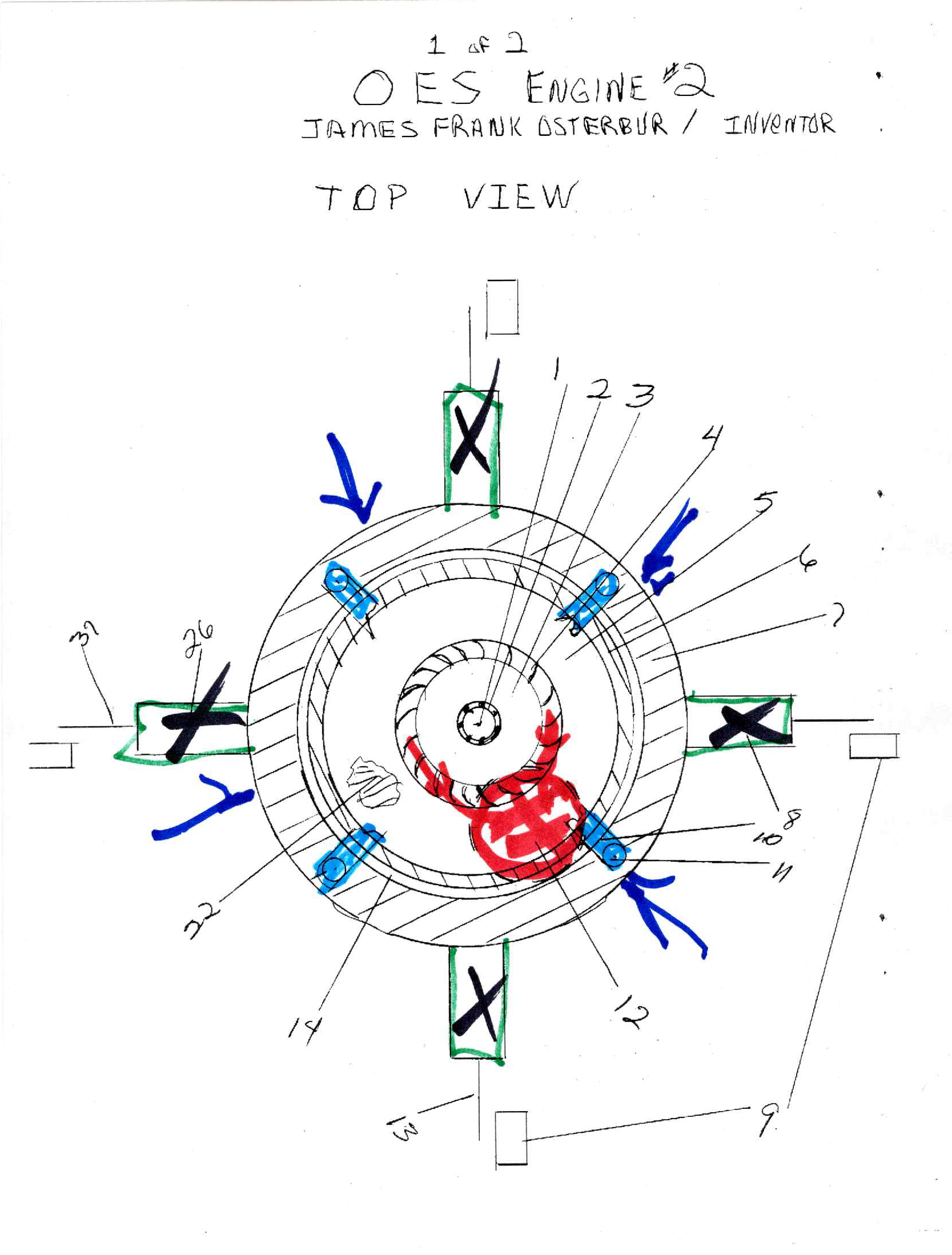
WE BEGIN with the top view drawing; which identifies the basic layout of the machine for electrical generation. This machine sets out as a horizontal conception, and is anchored to the floor by the four structural members #11 which contain it with cross beams #10 for holding the primary bearings #2 used to provide sustainable motion within the machine.
#1 is the structural base of the machine; a straight pipe upon which the machine rotates to create the revolving motion needed by industry. Bearings are fed along this pipe by pumping oil into the top of the pipe and letting that oil distribute itself throughout critical holes #25 in the piping. Which is then recollected in the sump area #36. piping follows the structure.
#3 in this drawing is the exhausting port but it detours around the bearing so as not to overheat it going out the dashed conceptual placement of #12 exhausting goes through the turbine as is #4 and it is shielded and contained within the housing #5
#6 is an exposed view of the rotating wheel valve: normally under the shielding. This is, for an understanding of placement. And bears no realistic alteration of the upper enclosing, housing.
#7 is the ring structure; but it does not contain any gate valve descriptions.
#8 & #26 represent 2 of 4 piston cylinders present in this drawing; #13 & # 31 represent a crankshaft in accordance with the piston cylinder as would be mounted onto the floor in this instance; preferably on slides. #9 represents the basic gearing or electrical motor/ generator as is attached to the crankshaft; as you desire it to be. A drawing too small, does not sufficiently help.
#14 represents the spacing between rotatory valving and ring structure
#22 represents a cutout in the upper shielding #5, to understand the valving/ and duct work itself is under this shield.
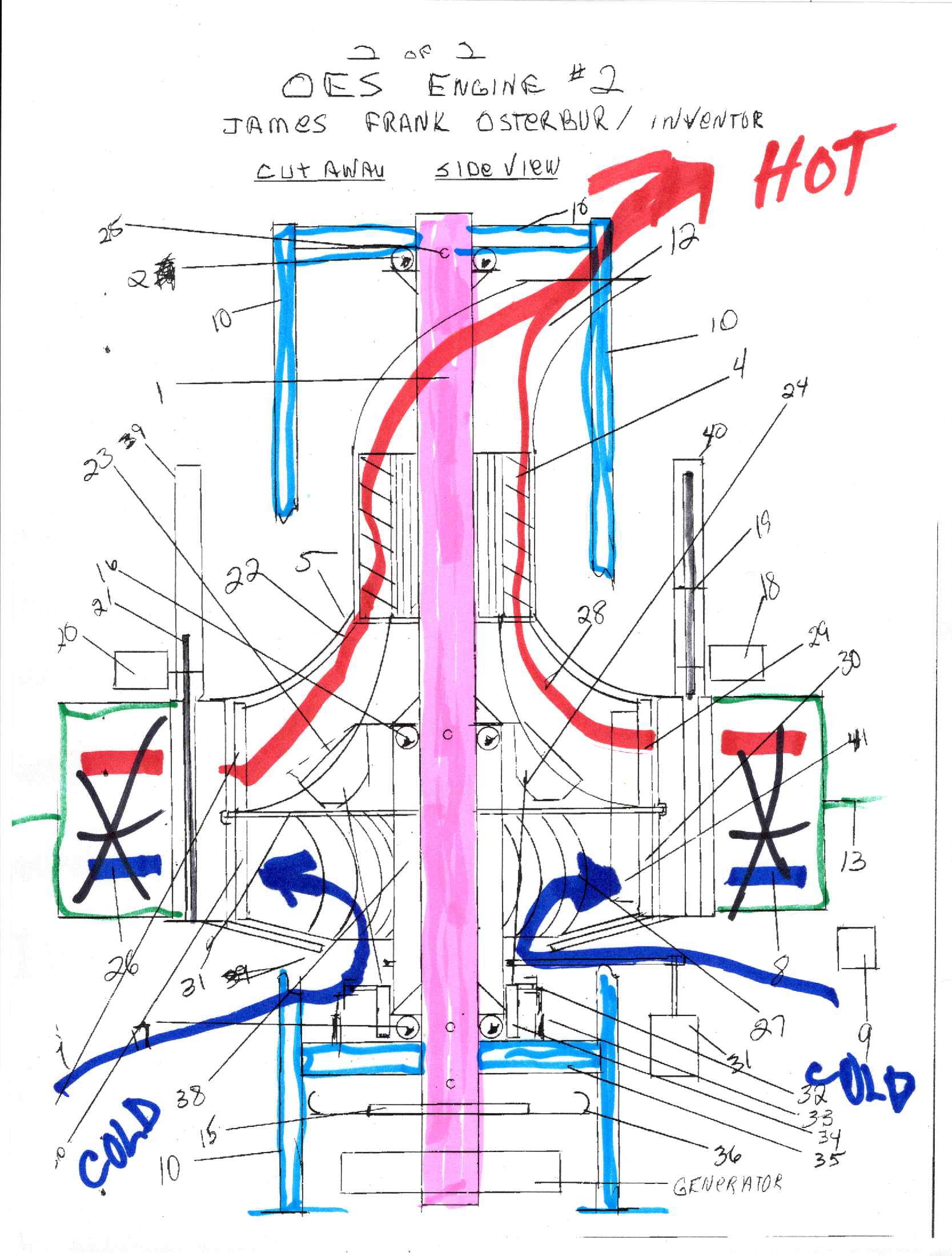
THE SIDE CUTAWAY VIEW OF OES, engine 2
in this drawing we look into the engine to discover the various parts at work. Numbers correspond to the top view above.
The two line and basic framework designated as #10 identify the common structural components being used. Reality knows the size of the machine will dictate how many along with design needs.
We begin at the base of the machine which is an electrical generator attached to the primary output shaft at #15. suitable methods for replacement of that component should be engineered in.
we then rise to examine the collection point for oiling; as would be dumped onto a flat plate that spins so the oil can be recycled and cooled before going back to the top. Or it can be used in the other direction; but will require sealing surfaces. Spinning the disk will separate out foreign particles; suitable methods for cleaning, housing, etc should be used.
#35 represents one of the structural components used in this machine, and it holds the machine itself through a bearing support #17. Which may or may not function to control the spinning rotatory valve as will.
What has not been adequately defined in this design until now is the use of vanes #23 within the combustion duct work. Operated by linkage #24 which is functioned through the collar #34. being forced up and down by the hydraulic cylinders as needed #33. it uses a rotating guide to interface the rotating and non-rotating parts (rather like a common vehicle clutch bearing is). More likely than a mechanical linkage along with its parts; is the use of an electrical drive of some kind to actuate the vanes going up or down as needed to vary the speed of rotation; with exhausting gases. These vanes are straight, curved, coiled over, hooked or whatever is deemed suitable to the job. Required although unneeded with constant work/ when the horsepower is altered so is the speed, and it is needed then.
#31 is a starter motor; and it is not properly placed or designed with a v-belt: because it is considered to be an almost irrelevant part. Once the machine is started it is not expected to be shutdown in electrical generation for years. A starter rope/ the generator at the bottom/ gearing or whatever you desire is your choice.
#38 structural collar; speed of the rotating valve is different than the output shaft therefore they are not attached, and are separated by bearings #16 & #17. this machine uses “half valving”. WHICH MEANS; the lower half #30 inlet; is different than the upper half #29 outlet. They are divided in the middle; separated from each other by shielding #31 which does enter the ring structure to form at least in part; a labyrinth seal. The lower inlet turbine for forcing combustion air into the cylinder#27 begins at the lower shield #39. air is then forced into the cylinders as the valve opens.
To shut off a cylinder a rotating or slide gate is used as shown in this version: #20 & 18 actuate the valve positioning (one up and one down). Valve plate is #21 & #19. the housing #31 & #40 are used to contain loss of pressure.
Combustion gases are exhausted through #29 into the duct work area of #28, and expelled through turbine #4
the use of a stiffener truss #41 (as needed), may be required to support and restrain the rotary wheel valving surfaces. Along with weight control over this part of the machine as well. Only one is shown.
THE CLAIMS: OES Engine 2 /James Frank Osterbur/ inventor-owner
- CLAIM: Combining units/ altering units to create more compact or specialized, units IN THE OES designs or definitions of this machine, in any and all ways; are as described and defined by the potentials; whether horizontal or vertical expressions, of this machine.
- A device according to claim #1; a machine which incorporates a divided rotating valve wheel that uses a labyrinth style intrusion into the ring structure to accomplish that fact.
- A device according to claim #1; a machine which can be built with sectioned inlet and outlet valving surfaces; to accomplish building bigger machines.
- A device according to claim #1; A machine which potentially, uses a spinning disk to create the filtering effect of oil in a combustion engine.
- A device according to claim #1; a machine which incorporates a stiffening truss as needed into the valving structure, which uses #31, the dividing shield to build off of.
- A device according to claim # 1; a machine which directs the flow of combustion gases into the turbine, either directly: as shown in the side view or by moving the turbine to “off structure” work; not shown.
- CLAIM: A machine which uses vanes located within the combustion gas duck work of the rotating wheel valve; to regulate speed and thereby the combustion process.
- A device according to claim #4; A machine which incorporates mechanical activation of those vanes to lower, turn, raise, shape, or whatever is required to regulate the speed produced by varying forces; to turn and control the combustion process.
- A device according to claim #4; A machine which can use electrically/ mechanically controlled changes in vane dimensions; either by commutator means or some function of providing current from the generator through the main shaft.
- A device according to claim #4; A machine which can use various forms and means of starting its operational process.
- A device according to claim #4; A machine which houses the gate valving partitions, to contain pressures.
- A device according to claim #4; A machine, which protects the bearings from excess heat by placing them appropriately.
- CLAIM: that units, complete machines; can be stacked together to form larger horsepower units working in tandem or not.
- A device according to claim # 12; whether face to face/ or back to back/ or in sequence, a line of units functioning as the same; has no effect on the outcome of unit work.
- A device according to claim # 12; a machine which incorporates a muffler incorporated, cooling housing by building it off the structural components of the unit itself, or in tandem as required.
- A device according to claim #12; a machine used in operation, 4- cycle, that presents primary gearing for the operational aspects of tying it together into one primary power output shaft: which is locked together to power the generator first; turbine is secondary in this arrangement.
- A device according to claim #12; a machine used in 2-cycle which uses the turbine as primary revolving input power; for the output shaft.
- A device according to claim #12; a machine which uses alternate power sources to create the necessary influx combustion air/ providing duct work to accomplish that goal
For a more detailed description of the images below please watch the video.